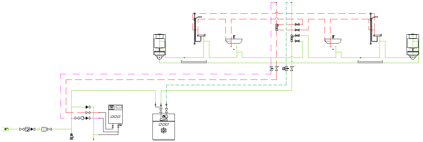
Circulation circuit
Each connection of a hot water circulation pipe (PWH-C) to a hot water consumption pipe (PWH) or a connection of a cold water circulation pipe (PWC-C) to a cold water consumption pipe (PWC) creates a circulation circuit. To ensure circulation of the hot or cold drinking water at the optimum energy level, only the volume flow required to maintain the temperature may flow in each circulation circuit. At least one thermostatic circulation regulating valve (e.g. a KEMPER MULTI-THERM or a KEMPER ETA-THERM) or one static circulation regulating valve (e.g. a KEMPER MULTI-FIX-PLUS) must be installed in each connection pipe and therefore in each circulation circuit.
In a circulation system, the flow paths start in the discharge connection of the circulation pump, run from there via a circulation connection to the consumer pipe and then end again in the suction connection. The flow paths(flow threads) form circuits in the circulation pump and are thus conceptually referred to as circulation circuits.