
Pipe network simulation
The Pipe Network Simulation window displays the pressure losses or the flow rates in the circulation flow paths.
The bidirectional link with the drawing and that the currently selected flow path in the drawing and and in the diagram. In the drawing and, the selected flow path highlighted in orange.
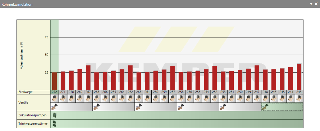
Below the flow path numbers in the Pipe Network Simulation window, thermal control valves, static control valves, circulation pumps, as well as drinking water heaters or cold water coolers are displayed.
- Right-clicking in the diagram takes you to further sub-options: Scaling:

You can display the diagram at different scales for a better overview. You can choose between the ‘Auto’ setting and defined values (25 %, 50 %, 75 %, 100 %, 200 %, 300 %, 400 %). The ‘Auto’ setting ensures that the project is always displayed in full.
Show tooltips:If you hover the mouse over an object in the diagram, technical data for the displayed object will be shown when this option is enabled.
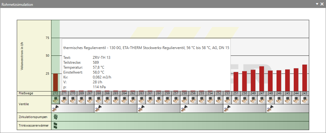
Show pressure losses:If this option is enabled, the pressure losses (blue bars) are displayed in the diagram.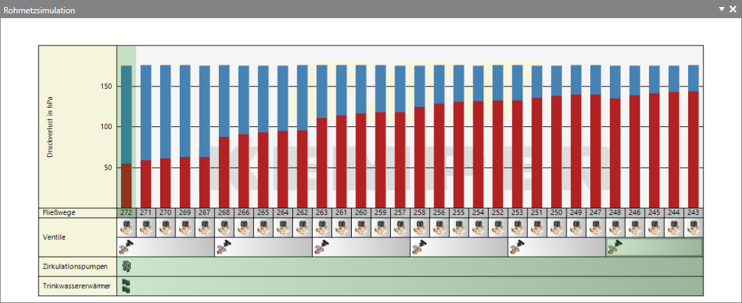
Clicking or double-clicking on the relevant symbols in the ‘Pipe Network Simulation ’ diagram displays diagrams and takes you to further dialogue boxes:
- Double-clicking on the flow divider icon
 takes you to the Flow Divider dialogue box if you have installed a flow divider in the hot water or cold water pipe.
 - Double-clicking on the valve icon, for example
 , displays the valve characteristic curve for the currently selected valve. Double-clicking takes you to the ‘Valve Settings’ dialogue box.
 - Double-clicking on the pump icon, for example
 , displays the pump network characteristic curve. Double-clicking takes you to the Pump Selection dialogue box.
 - Double-clicking on the domestic hot water heater or cold water cooler, for example
 and
and  , takes you to the Domestic Hot Water Heater dialogue box.