Cable with component connection

Draws a cable including component connection

Button:

Command name: SmartPipe

  1. In the building services toolbar, select the height level in cm from the Height levels in cm list for the connections in a floor plan drawing.
    Note:
    The set height level refers to the top edge of the finished floor.
    Tip:
    You can change the height level while executing the command. To do this, select a different height level after executing the command without ending the command. The new catch point will be found automatically.
  2. In the command options, select the connection type for the drinking water, waste water or heating trades.
    Tip:
    You can change the connection type while executing the command. To do this, select a different connection type after executing the command without ending the command.
    1. Select the desired connection type from the drop-down menu in the DHW trade.
      Note:
      If you have selected the connection type No connection, no component connection takes place.

      Possible connection types in the drinking water section:

      T-piece passage
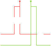
      Double wall disc
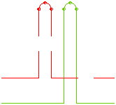
      Stub pipe
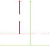
      T-piece outlet

      Thermal separator
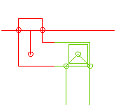
    2. Select the desired connection type from the drop-down menu in the waste water section.
      Note:
      In the waste water layer, it is necessary to draw in the direction of flow so that the chamfering takes place in the correct direction.
      Note:
      If you have selected the connection type No connection, there will be no component connection.
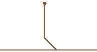
      Connection type in the waste water section:

      Chamfer 45°


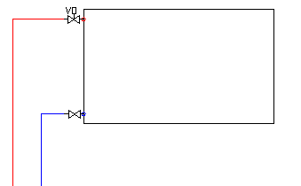
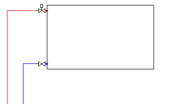
    3. Activate the Flow-controlled valve checkbox in the Heating section if you want to use a flow-controlled thermostatic valve.
      Possible connection types in the heating section

      With flow-regulated valve
      Without flow-regulated valve
  3. Select the maximum distances up to which the automatic connection should take place.
    Note:
    Connections can only be connected automatically if a perpendicular, straight connection to a suitable pipe can be created within the maximum connection length.
  4. Activate the Automatic layer checkbox if the line layer is to be adopted from the starting point.
  5. Select the starting point of the line by clicking in the drawing area. If you have set the starting point to a component connection or a line, the corresponding layer is automatically activated.
  6. Specify the end point of the line section by clicking with the mouse. If this is set vertically under a component connection, this component is automatically connected.
  7. End the command with the Enter key or by clicking the right mouse button.
You can find more information on our YouTube channel.

You can access the video here