
Pipe network simulation
The pipe network simulation window shows the pressure losses or the volume flows in the circulation flow paths.
The bidirectional coupling with the drawing ensures that the currently selected flow path is always selected in the drawing and in the diagram. The selected flow path is highlighted in orange in the drawing.
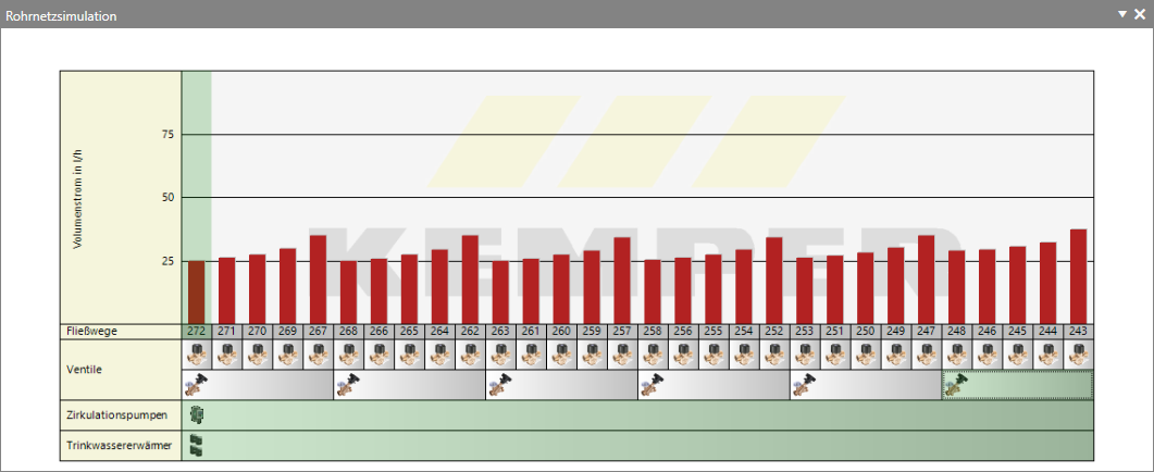
Thermal regulating valves, static regulating valves, circulation pumps and domestic hot water heaters or cold water coolers are displayed below the flow path numbers in the pipe network simulation window.
- Right-click in the diagram to access further sub-options: Scaling:
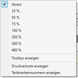
You can display the diagram in different scales for a better overview. You can choose between the Auto setting and defined values (25 %, 50 %, 75 %, 100 %, 200 %, 300 %, 400 %). The Auto setting ensures that the project is always displayed in full.
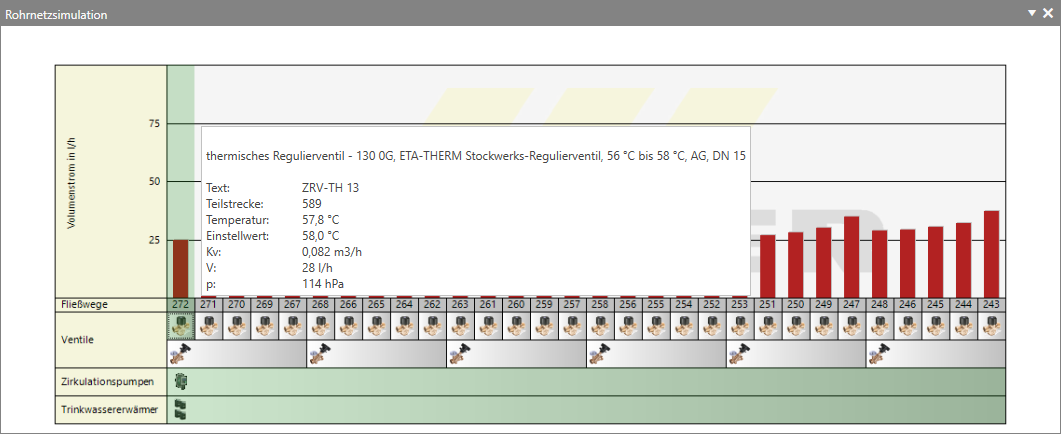
Show tooltips:If you move the mouse over an object in the diagram, technical data for the displayed object is displayed when this option is activated.
Show pressure losses:If this option is activated, the pressure losses (blue bars) are displayed in the diagram.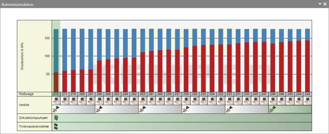
Click or double-click on the respective symbols in the Pipe network simulation diagram to display diagrams and access further dialogues:
- Double-click to open the Flow splitter dialogue if you have installed a flow splitter in the hot water pipe or cold water pipe.

- Clicking on the symbol shows the valve characteristic curve of the currently selected valve. Double-click to open the Valve settings dialogue.

- Clicking on the symbol shows the pump network characteristic curve. Double-click to open the Pump selection dialogue.

- Double-clicking on the DHW heater or cold water cooler takes you to the DHW heater dialogue.


Note:
If, after the simulation, a  sign becomes visible somewhere in the Pipe network simulation window, a message is displayed for the selected object in the Messages window.
sign becomes visible somewhere in the Pipe network simulation window, a message is displayed for the selected object in the Messages window.Tip:
If you have previously hidden the pressure curve, temperature curve and valve characteristic curve diagrams, click on and select the desired diagram.