
Ambient temperatures (DHW wizard options)
The respective ambient temperatures are of particular importance when calculating the cold water temperatures after a stagnation phase and the discharge times for overheated cold water. For this reason, the ambient temperatures must be determined on a project-specific basis depending on the installation conditions before the calculation.
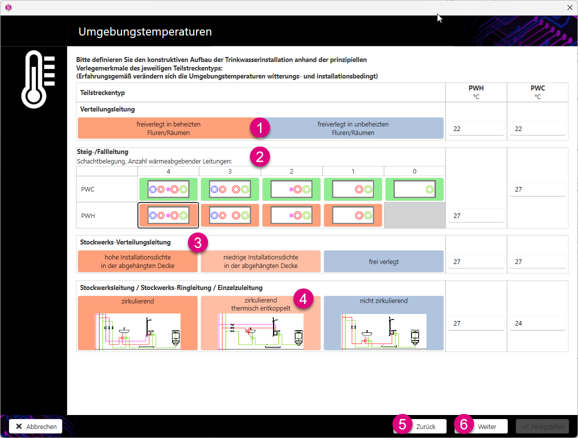
You can either enter the Ambient temperature for hot water (PWH) and cold water (PWC) in the input fields or click on the respective button to work with the default values and adjust them if necessary.
The planner is responsible for adapting the suggested values to the specific project, taking into account the local conditions.
- Distribution pipe area: You can specify the ambient temperatures here according to the installation of the distribution pipework. Exposed distribution lines in heated corridors or rooms result in higher ambient temperatures than exposed lines in unheated corridors or rooms.
Table 1. Suggested values for the ambient temperature depending on the type of installation Type of installation Default value PWH [°C] Suggested value PWC [°C] Exposed in heated corridors/rooms 22 22 Uncovered in unheated corridors/rooms 10 (worst case in winter) 15 (worst case in summer) - Rise/fall pipe area: Here you can specify the ambient temperatures according to the shaft assignment. Selecting the respective shaft assignments results in different default values for the ambient temperatures depending on the number of heat-emitting pipes:
Table 2. Ambient temperature depending on the duct assignment: Shaft assignment Default value PWH [°C] Suggested value PWC [°C] Four heat emitting pipes 27 27 Three heat emitting pipes 26 26 Two heat dissipating pipes 25 25 One heat emitting pipe 24 24 Without heat dissipating pipe 23 23 Note:If you only have one shaft for PWC and PWH, the same shaft assignment must be selected for PWH and PWC. - Floor distribution pipe area:
You can define the ambient temperatures here according to the installation density of your installation. With a high installation density in the suspended ceiling, the heat dissipation to the environment results in higher ambient temperatures than with a low installation density or a freely laid installation.
Table 3. Ambient temperature depending on the installation density: Installation density Default value PWH [°C] Suggested value PWC [°C] High installation density 30 30 Low installation density 27 27 Free installation 24 24 - Floor line / floor ring line / individual supply line area: Here you can define the ambient temperatures according to your desired installation type.
Table 4. Default values for the ambient temperature depending on the type of installation Installation type Default value PWH [°C] Default value PWC [°C] circulating 27 27 circulating thermally decoupled 27 24 non-circulating 25 24 -
With Back you can revise the settings you made previously.
- Click Next to go to the next step of the design definitions.
You can find more information on our YouTube channel.
