
Water abstraction simulation
Principles of water withdrawal simulation
The withdrawal simulation is primarily designed to prevent stagnant water and consists of a number of components. All these components (flushing valves, hygiene flushing systems, flow dividers, etc.) can be drawn and designed in the STUDIO calculation. Whilst the DIN-compliant calculation merely ensures that the minimum pressures and minimum flow rates are maintained at a given supply pressure, the water withdrawal simulation can determine the actual flow rates and, using these, calculate and display flushing times and flushing volumes.
Flushing is carried out as a cleaning flush in accordance with worksheet DVGW W 557.
Multiple consumers can be opened simultaneously; water withdrawal across pressure zones and extraction points can be simulated in the ring network. The water withdrawal simulation has two water withdrawal strategies with which the network can be simulated.
User interface of the water withdrawal simulation
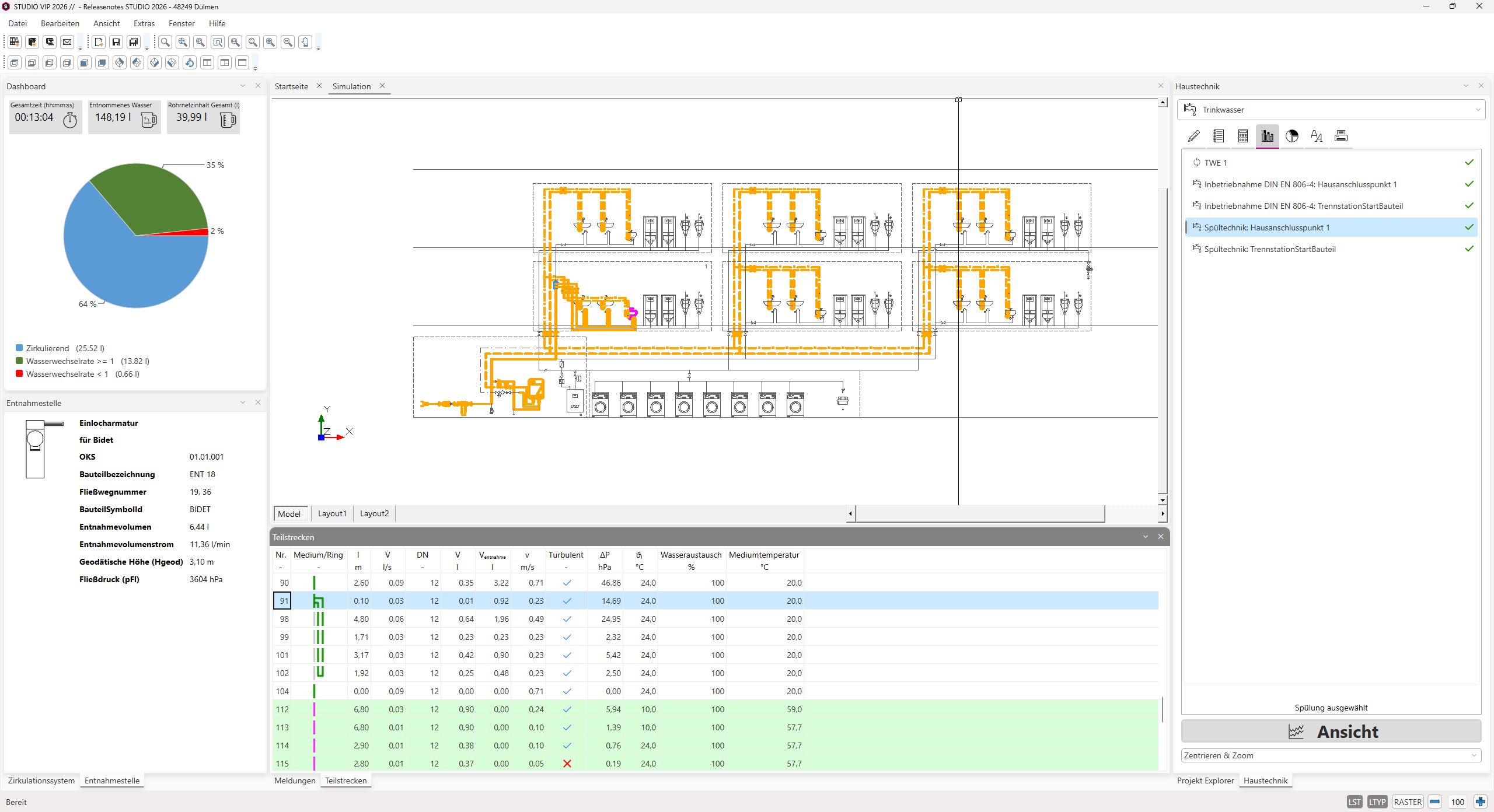
Water withdrawal strategies
The‘Flushing Technique’ water withdrawal strategy follows a specific sequence of withdrawals and is carried out as follows:
- Opening of all components of the flushing technique
- Supply line to the fire-fighting water transfer station
- Flushing system in Coolflow systems
- PWH flow paths
- PWC flow paths
- Flow paths to mixed-use outlets
- The criterion for termination is a single water exchange in all active sections.
Thewater extraction strategy forcommissioning 806-4 is carried out as follows:
- Opening of all tap points
- All extraction points are opened room by room.
- They are sorted according to flow path length, starting with the shortest flow path.
- Water intake points, disregarding flow rate limiters
- The termination criterion is a 20-fold water change in all sections where water is flowing.