
Supply pressure (design options for drinking water)
The ‘Supply pressure’ section under ‘Data entry ’ is divided into several subsections.
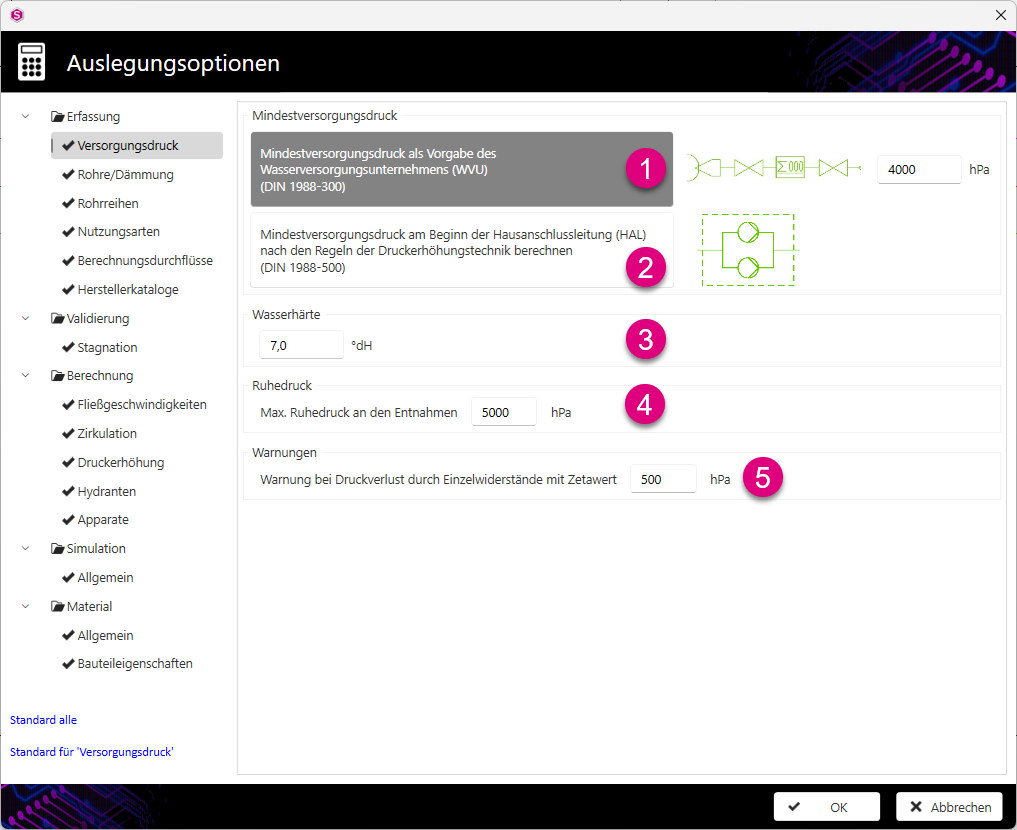
- Minimum supply pressure as specified by the ‘ Water supply companies ’ (WVU) (DIN 1988-300): Enter the minimum supply pressure in hPa here. The default value for the minimum supply pressure is 4000 hPa. As a rule, the minimum supply pressure specified by the water supply company must be entered here. To ensure that the WVU’s specifications can be taken into account, the house connection layout must be shown in a diagram accordingly.Note:If the pressure loss in the service connection pipe and in the water meter is to be taken into account as a flat rate of 850 hPa, the drinking water installation must begin in the diagram with the ‘service connection group’By default, the water supply company should specify the minimum supply pressure downstream of the water meter in accordance with DIN 1988-300. To ensure that this case is taken into account in the calculation, the service connection pipe and the water meter must not be shown in the diagram. In this case, the drinking water installation begins with the component ‘neutral starting or handover point’.
 combined component.Note:The flat-rate allowance for pressure loss in the service connection pipe and the water utility’s water meter, totalling 850 hPa, leads in drinking waterinstallations for multi-storey buildings to a low available pressure head and thus to unnecessarily large pipe cross-sections. These pressure losses should be calculated on a case-by-case basis, taking into account the water supplier’s specifications, particularly where Woltmann meters are used in larger drinking water installations.
If the water utility specifies the material and nominal diameter of the service connection pipe, as well as the design of the ‘ Main shut-off device ’ (HAE) and the water meter, the corresponding pressure losses can also be calculated on a case-by-case basis. To do this, the domestic service pipe – starting with the ‘domestic service connection point’ component (valve tapping clamp) – and the water meter assembly must be depicted in a diagram. The WVU specifications can be incorporated into the section properties of the service connection pipe or into the component properties of the respective fittings.
- Calculate the minimum supply pressure at the start of the domestic service pipe (HAL) in accordance with the rules of pressure-boosting technology (DIN 1988-500): If you select this calculation method, the ‘ Minimum supply pressure ’ is calculated as the product of the greatest flow path length and an average pressure drop.Note:By default, the specifications from the now-withdrawn DIN 1988-5 are used for the pressure drop. The pressure drop can be adapted to project-specific requirements in the design options under ’.
- In the ‘Water Hardness’ section, you define the inlet water hardness of the starting component in °dH.
- In the ‘Warnings’ section, you define the pressure loss based on zeta values, above which a warning is issued.
-
In the ‘ Resting pressure ’ section, you define the maximum at the tap points in hPa.
Further information can be found on our YouTube channel.
 Click here to watch the video – Drinking Water Pro Minimum supply pressure
Click here to watch the video – Drinking Water Pro: Principles of pressure-boosting technology