
Flow path data sheet (waste water)
The flow path data sheet in the heating trade provides brief information on the hydraulic conditions in the flow path.
The flow path data sheet is made up of various components.
| Components in the flow path data sheet | Explanation of the individual components |
|---|---|
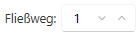
|
The input field shows the number of the selected flow path. The flow path number can be entered manually or set using the arrow keys.
Tip: Alternatively, you can select the desired flow path in the drawing and display its details. You can set the zoom behaviour in the drawing using the drop-down menu in the Building Services window under View. |

|
The medium abbreviation of the selected flow path is displayed next to the flow path number. The background colour reflects the layer colour in the drawing. |
| Location area | Displays information on the location of the flow path, for example the roof area or the room area. |
| Lead-in point area | Displays the name and product image of the entry point in the flow path. |
| Hydraulics area | Displays information on the hydraulic conditions. Various information is displayed according to the selected flow path. The following information is displayed for gravity drainage: The following information is displayed for siphonic drainage systems:
|