
Temperature profile in the edge and occupied zone in the integrated design
According to DIN EN 1264-3, the edge zones with an increased surface temperature (up to 35 °C) are generally located on the outer walls of a room and may have a maximum width of 1 m. As in section 4.1.3 of DIN EN 1264-3, the design is based on the higher limit curve for (ϑF,max - ϑi) = 15 K. The temperature spread in the boundary zone for series connection with a heating circuit is selected in accordance with DIN EN 1264-3 by ensuring that the calculated flow temperature from the lower limit curve for series connections with a heating circuit in the occupied zone is not exceeded when the heating water enters the occupied zone from the boundary zone.
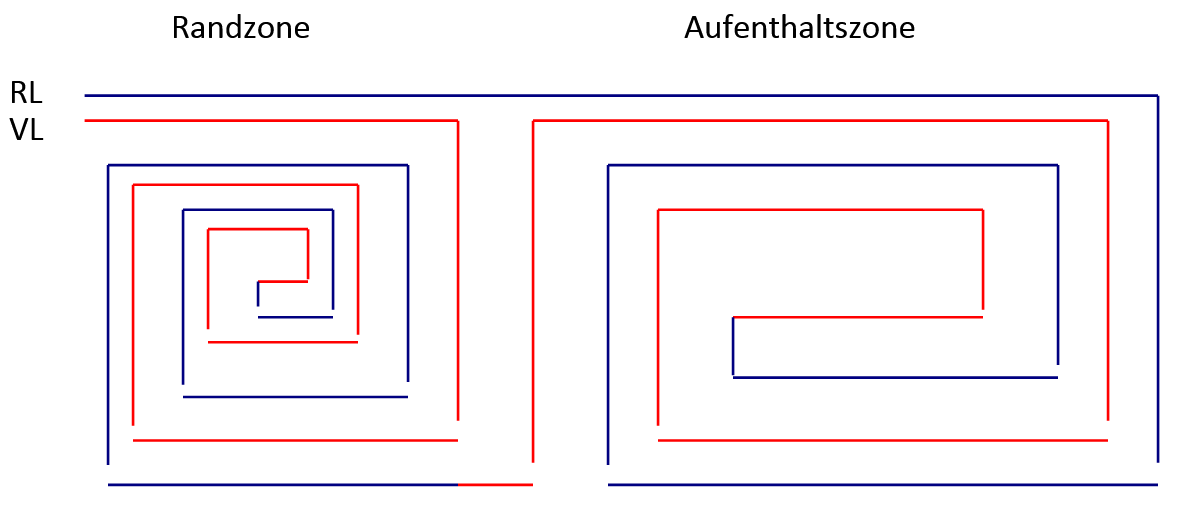
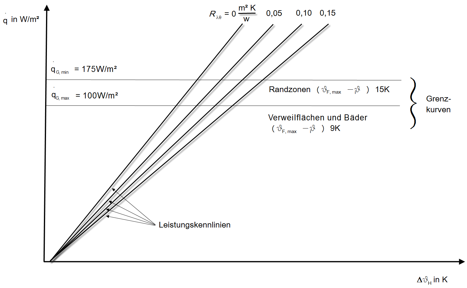
The limit curves are used to determine the maximum permissible flow temperature. The following physiologically permissible limit values apply for the maximum floor surface temperatures:
-
29°C for occupied zones
-
35°C for peripheral zones
Furthermore, a division of the system is used in which the specific output (W/m²) does not exceed the limit value qG,max from Figure 2.
The following limit values apply here:
-
qG,max = 100 W/m² for dwelling areas
-
qG,max = 175 W/m² for edge zones
This results in the factor qRZ/q AZ = 1.75. This factor can be changed in Dendrit STUDIO. Dendrit STUDIO then attempts to adjust this via the division.